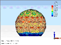
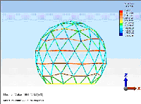
 | Radome Structural Analysis Role of General Buckling |
- Introduction
- Wind Speed and Pressure Dynamics on Radomes
- Role of General Buckling
- Case Example 1: Critical Buckling Wind Speed Dependence on Radome Geometry.
Quasi-Random vs. Symmetric Orange Peel - Case Example 2: Critical Buckling Wind Speed Dependence on Sandwich Core Thickness.
- Case Example 3: Critical Buckling Failure Wind Speed Dependence on Framework and Thin Membrane Material. Dielectric vs. Metal Space Frame Radome
- Case Example 4: Structural Analysis of 41ft (12.6m) Diameter Thin Membrane Geodesic Dielectric Space Frame Radome. Design Criteria Wind Speed 200 mph (322 km/hr). Snow/Ice Load 50 lb/ft2.
- General Bucking Safety factors
-
Table of Contents
 Introduction
Radomes protect antenna systems from wind, blowing sand, snow, ice, rain, ultra violet sun light, temperature, fungus and corrosion. In particular, wind, snow and ice loads place stringent demands on the structural properties of the radome. To support these environmental forces, radome structures are composed of panels, which when assembled form a truncated spheroid. Panels may be spherical sections or flat facets forming orange peel, triangular, hexagonal, pentagonal or other various panel shapes. To enable adjacent panel assembly, each panel is surrounded by a flange, which creates a radome framework characteristic of the different panel shapes. This framework may also have structural properties as is usually the case for geodesic radome designs. Degrading RF system performance, the framework also scatters electromagnetic energy into the antenna sidelobes and introduces transmission loss. Framework scattering loss accounts for most of the radome transmission loss being 4 to 100 times larger than the wall insertion loss. To minimize electromagnetic, RF degradation, radome structural strength must be measured against the demands for better RF performance. What this means is that the radome structure supporting the wind, snow and ice loads must be strong enough to meet environmental requirements for the radome lifetime. Beefing up the radome panel framework even more or making the wall sturdier just degrades RF performance. To enhance RF performance, this balancing act between a stronger structure with heavy-duty sized members and RF performance determines that radomes are designed as an electrical filter constrained by structural safety factors over the radome lifetime. It is for this reason that AFC defines radome structural safety factors by a criterion based on the General Buckling geometric deformation of the radome shell leading to catastrophic failure wind speed and collapse of the radome.This memorandum shows that radome catastrophic failure is a characteristic of General Buckling, which depends on the complication of all the properties of the radome shell. From radome geometry and panel shape and size to framework and wall material properties, each of these characteristics impacts General Buckling and the critical wind speed at which radomes fail. Without knowledge of General Buckling, if the unsuspecting radome is designed alone for just stress and strain, it would actually collapse at significantly less wind speed or snow loads as determined by General Buckling.
 Wind Speed and Pressure Dynamics on Radomes
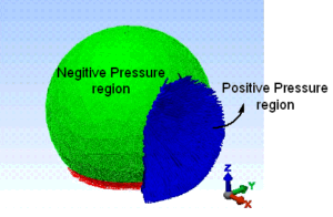 |
| Figure 1. Turbulent wind pressure over radome surface. |
 Role of General Buckling
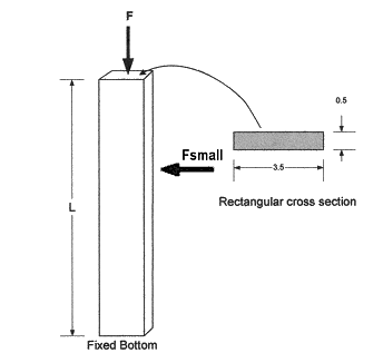 |
| Figure 2. General Bucking of a Rectangular Column. |
Fcr= π2EI/4L2,
where E is Young's modulus. The failure force, Fcr at which the beam collapses is given the name “Critical General Buckling Force.” In other words, when the column length is twice as long (2L), the failure occurs at 1/4 the load. More too, the failure load Fcr decreases even more rapidly when a second small force Fsmall is applied perpendicular to column.Like the column, a radome structure is a framework structure of interconnected columns (beams). See Figure 3. As with the simple column, the framework members are also interconnected by a wall, which applies perpendicular forces on the column beams. Clearly, the radome represents a complicated General Buckling problem that defies analytical solution. Recognizing the approximate nature of the early analytic approximate solutions, engineers introduced a safety factor into the General Buckling solution.
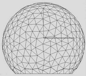 |
| Figure 3. Radome structure of interconnected beams with perpendicular wall related forces. |
![]()
With the advent of computers, powerful structural analysis software became available that enabled complicated structures, such as radomes, to be analyzed for their survival in high winds or under snow loads. Such software goes by the name Finite Element Analysis or FEA for short. Using time-dependent nonlinear FEA, one can trace how a radome fails over time when it is subjected to high-speed wind or significant snow and ice accumulation. With FEA analysis tools, General Buckling failure modes are determined at wind speeds or snow loads several times less than that would be predicted from stress and strain calculations alone. Radome geometric deformation by General Buckling failure is a global system property of the entire radome structure. Indeed, General Buckling depends on the complexity of radome diameter and geometry, panel shape and size, framework and wall material properties and dimensions. The next several Case Examples demonstrate the influence of the radome geometry type and of the choice of panel wall and framework material on General Buckling.
 Case Example 1: Critical Buckling Wind Speed Dependence on Radome Geometry
Quasi-Random vs. Symmetric Orange Peel
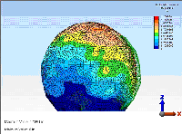
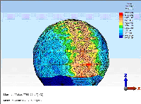
Radome geometry is one of the most important parameters in determining the critical buckling failure wind speed. Table 1 compares the design choice between the quasi-random and symmetric orange peel radome geometry. For a sandwich 35ft (10.7m) diameter radome example, Table 1 shows that a quasi-random radome geometry is significantly stronger than the symmetric orange peel geometry. The quasi-random radome is 219 percent stronger than the symmetric orange peel unit and has an appropriate safety factor of 2.19 for a 150 mph (241km/hr) specification wind speed. In contrast, the symmetric orange peel radome only has a 1.0 critical buckling safety factor. For a safety factor of 2.0, the symmetric orange peel radome is only useful to a 106 mph (170 km/hr) de-rated design wind speed requirement. Table 1 analyzes sandwich radomes with 0.5 inch (12.7mm) core thickness for operational frequencies up to 5.0 GHz.
| Radome Geometry | Critical Buckling Wind Speed | Safety Factor at 150mph Wind Speed | Picture |
| Quasi-Random | 222 mph 357 km/hr |
2.19 | 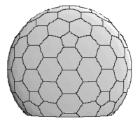 |
| Symmetric Orange Peel | 150 mph 241 km/hr |
1.00 | 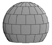 |
|
Case Example 2: Critical Buckling Wind Speed Dependence on Sandwich Core Thickness |
Sandwich radome design depends on both the maximum frequency of operation and wind speed specifications. From Table 2, as the sandwich core thickness increases, the critical buckling failure wind speed increases as well as the safety factor margin. Note that the maximum operating frequency simultaneously decreases inversely proportional to the core thickness. Therefore for a constant critical buckling safety factor, the radome wind speed specification must decrease with increasing operating frequency. As an example from Table 2, the 0.25 inch core thickness radome critical buckling wind speed is 180 mph (290 km/hr) with a safety factor of 1.44. For a critical buckling safety factor of 2, this 9 GHz design is inadequate. The radome wind speed specification requirement should be reduced to 127 mph (204 km/hr).
This analysis is for a 35ft (10.7m) diameter quasi-random radome.
| Radome Core Thickness | Critical Buckling Wind Speed | Safety Factor at 150mph Wind Speed | Maximum Von Mises Stress within Panels at 150 MPH (lb/in2) | Worst Case Stress within Framework 150MPH (lb/in2) | Maximum Frequency of Operation | Picture |
| 0.25 inch 6.4 mm |
180 mph 290 km/hr |
1.44 | 916.25 | 765.21 -1005.71 |
9.0 GHz |  |
| 0.5 inch 12.7 mm |
222 mph 357 km/hr |
2.19 | 814.76 | 572.12 -981.41 |
5.0 GHz | |
| 1.0 inch 25.4 mm |
290 mph 467 km/hr |
3.73 | 780.18 | 526.30 -956.91 |
3.5 GHz |
| Case Example 3: Critical Buckling Failure Wind Speed Dependence on Choice of Framework and Thin Membrane Material |
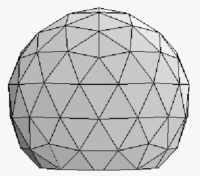
Space frame radomes are assembled from panels, which are composed of a structural framework with an attached thin membrane wall. For the Dielectric Space Frame (DSF) radome, the radome panel framework and thin membrane walls are laminated one piece monolithic units manufactured form Fiberglass Reinforced Plastic (FRP) materials. The panel flanges form the radome framework. In contrast for the Metal Space Frame (MSF) radome, the thin membrane wall is attached to an Aluminum metal framework. To accomplish the attachment process, the membrane material must be very pliable. The usual material choice is Dacron. While dielectric space frame FRP radomes have a rigid membrane wall, a Dacron membrane wall metal space frame radome is easily recognizable by flapping panel membranes. At moderate wind speed levels, metal space frame radomes require pressurization to reduce membrane oil-canning, sound/vibration noise, microphonics and fatigue failure. Table 3 demonstrates the role that critical buckling plays for identical 41ft (12.6m) diameter geodesic quasi-random space frame radomes. In each case, the framework member size (width and depth) is the same for both radome types. Just Aluminum material properties are substituted for the FRP material. And Dacron thin membrane wall material properties are substituted for FRP.
Clearly Aluminum is stronger than FRP. One would expect the Aluminum framework strength to dominate the structural analysis results. Yet that is not the case. The panel membrane material has a significant and major role in determining the critical buckling failure wind speed. Due to the panel membrane material, observe from Table 3 that the dielectric space frame radome is 150 percent stronger than the metal space frame unit. While the dielectric space frame radome 2.5 safety factor is adequate for a 200 mph (322 km/hr) wind speed requirement, the equivalent metal space frame radome has only a 1.0 safety factor. In order to increase the metal space frame critical buckling safety factor to 2, one must reduce its rated wind speed to 142 mph (228 km/hr).
The only way for the metal space frame radome to safely meet a 200 mph (322 km/hr) specification wind speed is to increase the Aluminum framework member size or change the membrane to a stronger material. Since a flexible membrane material is necessary for the fabrication of the metal space frame panel, there is little choice but to stay with Dacron. The only decision available for the metal space frame radome is increasing the Aluminum framework members’ size.
There is, however, a penalty to pay for increasing the Aluminum framework size. The penalty comes in the form of a simultaneous increase in transmission loss and deterioration of RF performance. We refer the reader to AFC’s Transmission loss and Antenna Pattern Degradation web page.
Table 3 clearly shows that all properties of the radome are important in determining radome collapse at the critical buckling failure wind speed. Structural critical buckling safety factors dominate the compromise between a stronger structure with heavy-duty sized members and RF performance.
Dielectric vs. Metal Space Frame Radome
Radome Design Parameter
Dielectric Space Frame Radome
DSFMetal Space Frame Radome
MSFPicture
Flange Framework Material
FRP
Aluminum
Panel Membrane Material
FRP
Dacron
Critical Buckling Wind Speed
316 mph
509 km/hr201 mph
323 kn/hr
Safety Factor at 200 mph Wind Speed
2.50
1.01
| Case Example 4: Structural Analysis of 41ft (12.6m) Diameter Thin Membrane Geodesic Dielectric Space Frame Radome. |
Table 4 provides the time Dependant nonlinear FEA structural analysis data for a 41ft (12.6m) diameter dielectric space frame thin membrane radome designed for 200 mph (322 km/hr) wind speed and 50 lb/ft2 snow/ice loads. In particular, Table 4 identifies the critical buckling wind speed and snow load, safety factors for critical bucking under wind and snow loads, Von Mises safety factors for membrane stress, safety factors for worst framework stress and radome displacement under maximum loads.
As stated earlier, please note that the critical buckling safety factor for wind speed is the smallest safety factor in the structural analysis set and the chief requirement for radome structural integrity. From a design point of view, if the critical bucking safety factors are adequate, then the other safety factors are easily met. In contrast, the opposite is not true. Should one design just for stress and strain Von Mises and Worst Framework Stress criteria, then the radome may be subject to catastrophic collapse at significantly less wind speed and snow loads.
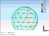
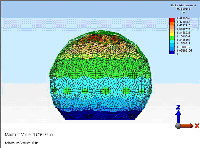
Figure 4 pictorially displays the radome displacement, Von Mises membrane stress and the framework stress for the radome at 212 mph (342 km/hr) wind speed and 50 lb/ft2 snow loads. For better viewing, each picture maybe enlarged by clicking on the image.
Thin Membrane Geodesic Radome
Critical Buckling Wind Speed
Safety Factor
Critical Buckling at 200MPHSafety Factor
Maximum Von Mises Stress within Panels at 200MPHSafety Factor
Worst Framework Stress at 200MPHMaximum Radome Displacement at 200MPH
316 MPH
(316/200)2 = 2.5
29651/8719.6 = 3.4
29651/9738.6 = 3.0
1.3 inch
Critical Buckling Snow/Ice Load
Safety Factor
Critical Buckling at 50 lb/ft2 Snow/Ice LoadSafety Factor
Maximum Von Mises Stress within Panels at 50 lb/ft2 Snow/Ice LoadSafety Factor
Worst Framework Stress at 50 lb/ft2 Snow/Ice LoadMaximum Radome Displacement at 50 lb/ft2 Snow/Ice Load
272 lb/ft2
272/50 = 5.4
29651/1968.3 = 15.1
29651/1881.4=15.8
0.52 inch
 General Bucking Safety Factors
Antennas for Communications (AFC) has been deploying radomes worldwide since 1987 and composite material antennas since 1972. Our radomes have been subjected to every environmental condition. Over the years, many of these radomes have also been subjected to hurricane, typhoon and cyclone winds. Each of these radomes experience constant environmental exposure to sunlight, UV and corrosive atmosphere as well as the inconsistencies of manufacturing tolerances, installation errors and infrequent maintenance. End-of-life issues generally characterize this slow degradation process. Using natures environmental test laboratory as a guide, we have analyzed these successful radome deployments using the time dependent nonlinear FEA tools at our disposal. Our concern is how much safety factor margin do we need to guarantee a life-time of structural performance. Based on those FEA analyses, we come to the following criteria on critical bucking safety factors:
- Large Radomes > 1.9
- Small Radomes > 4.0
-
General Buckling Safety Factor Criterion
AFC manufactures, markets and sells worldwide satellite dish antennas, conical horn antennas, radomes, antenna feeds, microwave and waveguide components, ultra low loss waveguide transmission line Tallguide ®, and shelters. Our customers serve the broadcast, communications, radar, weather and cable industry, defense, government, and government agencies worldwide. AFC's quality control manufacturing standards are certified under ISO 9001 : 2015.
For more information on AFC's radome product line, please refer to AFC's Radome Network Home Page on dielectric radomes. A complete Internet WWW AFC document index may be found in Antennas for Communications (AFC) Home Page Document Summary List.
Return to AFC ProfileReturn to AFC Home Page Return Radome Network Home Page
Tel (352) 687-4121 Fax (352) 687-1203 Email sales@afcsat.com
Tallguide is a Registered Trademark of Antennas for Communications
Copyright © 2005 - 2020 Antennas for Communications
